
Tire Razor Part 2
The Lathe
By
Eric Cropper
This is the second installment of the Tire Razor product line.
If you didn’t see the original review of the Tire Razor you can find it here.
If you purchased a Razor, you’ve probably already spent hours getting the wheels and tires of your slot fleet trued to perfection. Maybe, you just got a box in the mail with a couple of new rides that need some Razor TLC. Then the Razor sits until the arrival of its next victim.
Maybe, it doesn’t have too.
Do you use after market metal wheels?
Did you scratch build that perfect car from a model kit?
Tired of your press-fit plastic wheels coming off during a race?
Got a stock plastic wheel that has a broken hub that can’t be repaired?
The Tire Razor Lathe might be for you if you answered yes to any or all of these questions.
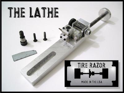
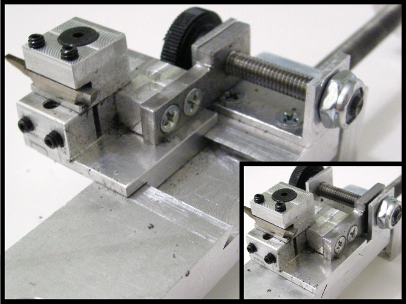
The title shot above gives you an overall peek at the Lathe and all that comes with it. It’s made out of the same aircraft grade aluminum as the Tire Razor and is another handmade product. So, again remember that there might be a wait if and when you decide to order one for yourself. Time for a closer look…
360 Look of the Lathe
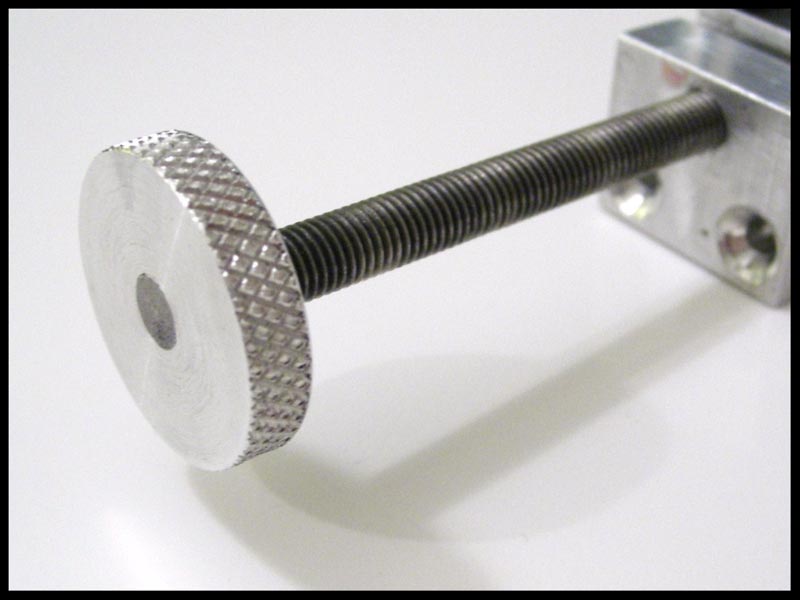
Above is the control knob for the side to side axis that moves the bed of the cutter. A nice textured knob to prevent finger slips and added control for fine movements.
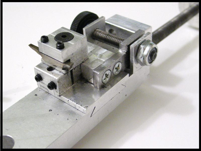
Below is the front of the cutter. This is the side of the lathe that faces the wheel you’re cutting down. I’ll cover the various screws and their functions later in the review. Yes, it’s dirty. I took the pictures after using it. Also, yours will arrive dirty just like your Tire Razor. Jon personally tests each item he makes before it is shipped to its new owner.
Below is a different view of the front side of the lathe and in the foreground you can see the side mounting bracket.
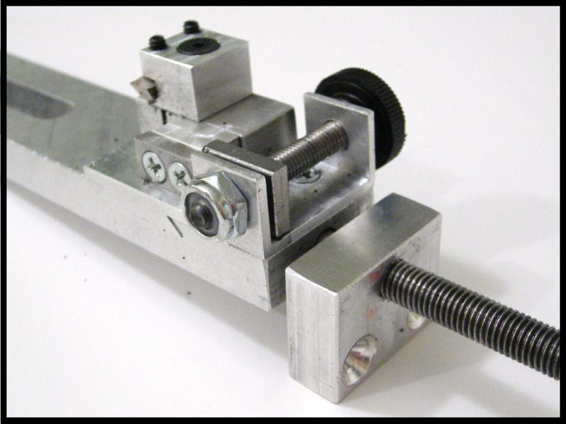
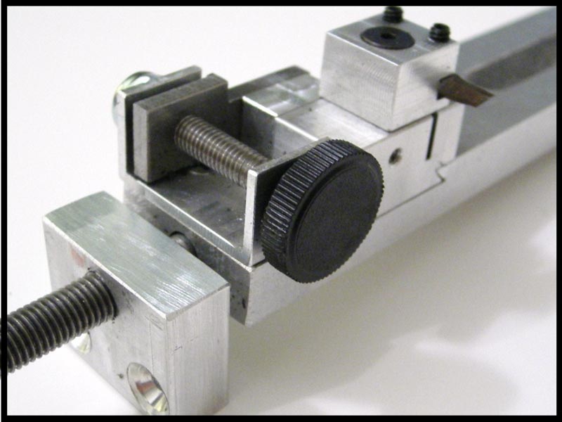
Above is the backside of the cutter and the threaded black knob controls the forward and reverse of the cutter base.
This concludes the 10 cent tour. You now ask, “How does this thing mount to my Razor?” It’s as simple as 1-2-3.
Mounting System
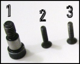
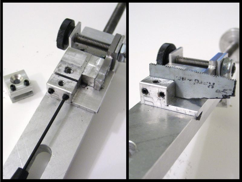
Above is 1-2-3. #1 is the slide mount bolt for lack of a better term. #2 and #3 are your side mounting bracket screws.
The order that you use these to mount your lathe isn’t important, but below is how I do it.
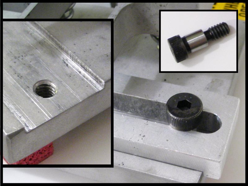
The lathe simply fits in the channel where the Tire Razor’s sanding block usually resides. You will see the bolt hole on the right side of the channel. This is where the slider mounting bolt is used to hold the bed of the cutter in place. Slide the lathe into the channel and screw the bolt into this hole through the opening of the lathe bed. This bolt has an opening to use a #4 Hex Driver. However, you don’t need it when you install this bolt. You just want to hand tighten the bolt and you want it just tight enough to help keep the bed of the lathe in the channel of the Razor.
Next, we are installing the side mounting bracket with screws #2 and #3. Hold the bracket to align the holes in the bracket with the screw holes in the side of the Razor. Start the screws by hand to avoid cross-threading. Once you get them started you can switch to a #2 Hex Driver to finish the job and snug up the screws against the side of the Razor. Snug is all you need. So, don’t over tighten these screws. NOTE: You might have to mess with the position of the large knob control to get your hex driver in place for these screws.

Below is the fully mounted lathe attachment on the Tire Razor. I told you it was easy. This view gives you a better idea of how it all works. The large control knob on the left of the picture moves the lathe bed and mounted cutter side to side just as you would move the sanding block side to side with your hand. The black control knob moves the cutter base forward to cut the wheel and backwards to your starting position.
The Cutter
The pictures above show the range of movement for the cutter base. As you turn the black control knob, the threads turn through the cutter base mounting bracket located on the front with the 2 Philip screws in the photos above. NOTE: There is no need to mess with these Philip screws. There’s a large amount of distance front to back, but I doubt you’ll ever come close to needing it.
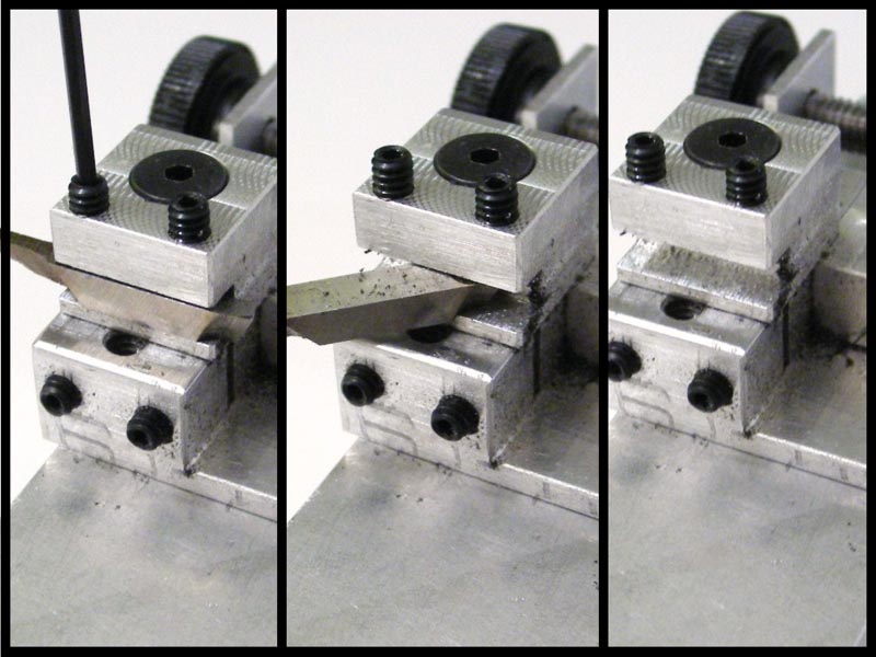
Below is a series of photos showing how to remove the cutting blade. The 2 set-screws on top of the cutter base accept a .050 Hex Driver. You don’t have to completely remove them in order to remove the cutting tool. Simply, do the reverse to install the cutting tool. Don’t over tighten.
The cutter base can also be removed from the lathe and repositioned to cut down larger width wheels. The screw used to remove and mount the base requires additional use of the #2 Hex Driver. The screw hole on top of the small rectangle section in the bottom right is the 2nd mounting position for wider wheels.
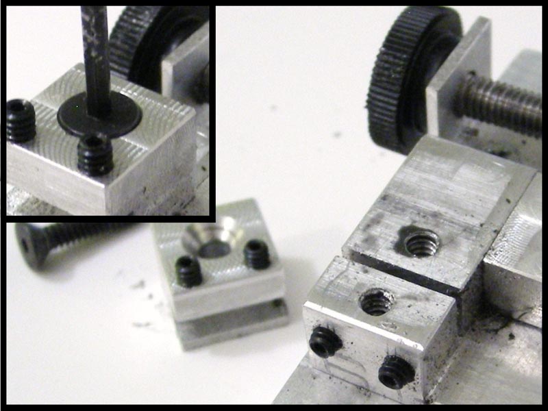
This shot shows the cutter base in the 2nd mounting position. I’d guess you gain around a quarter of an inch of clearance in this position.
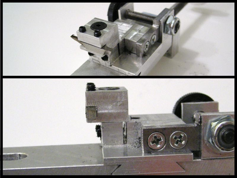
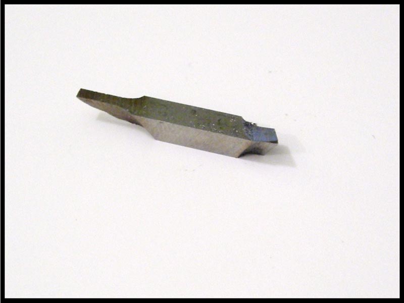
Above are the cutting tools. I say tools because this is actually a 3 in 1 cutting tool. The left side in the photo is what Jon called a separating tool.
The right side, depending on how you rotate and mount the cutter, is either a right or left handed cutter.
Below with the cutter base removed there is a mounting slot for another tool to be used with the lathe. A small saw blade is also included and can be mounted in the groove pictured below and held in place with 2 set-screws. They are the same .050 Hex Driver set-screws used to hold the cutting tool in place. This saw can be use to cut the face off of the turned down wheel to create the wheel insert. Although, looking at the picture I’d say it should be mounted with the angled bottom section between the screws. That would give you a better angle to cut the face of the wheel off. Honestly, Matt just grabbed a utility knife and cut it off by hand. However, if you don’t feel comfortable using a knife, this would be the way to go.
Prep Time
If you are cutting down wheels mounted on a knurled axel, such as, Carrera and Scalextric there’s no prep time before you start cutting down the wheel. However, if you are cutting down a wheel that is press fitted on a smooth axel, such as, Ninco or in my case Powerslot, you will need to glue the wheel onto the axel. We actually had to stop and glue the wheel two more times during the cutting process.
I suggest that you use an axel stop if you can remove a wheel to fit it on the axel. When it’s locked into place against one of the bushings it will help keep the axel assembly from moving side to side when the cutting tool is cutting into the wheel. We didn’t originally use one. You will see in one of the videos that the axel is moving with the cutting tool and Matt pushes on the wheel with his finger to finish the cut across the wheel. DON’T DO THIS…LOL. You’ll hear Matt say, “That’s rough on the finger.” (shaking my head)
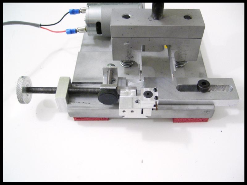
Okay, now mount the axel assembly into the Tire Razor’s brackets as shown in the Tire Razor review. Remember to LUBE the axel bushings before you turn on your Razor. This is a very important step whether you’re just truing your wheels and tires or using the lathe.
Let the Plastic Fly
Okay, I’ve told you what knobs control what and that you can cut left or right. What else do you need to know, right? Turn up the power!!! We started at 6V and that wasn’t cutting it. If the tip of the cutting tool dug in too quickly it broke the glue bond and the wheel was spinning on the axel. We took it all the way up to 8V and eventually settled on 12V.
Now what? I wish I had a definitive answer for you, but I don’t. It’s a trial and error process to get the feel for the lathe. How much do I take the cutting tool forward? How fast or slow do I turn the horizontal control knob? It will be up to you to figure that all out. All I can say is turn the power on, turn the black knob slowly until you hear and/or feel the cutting tip against the wheel and now start turning the large silver (horizontal movement) control knob until you’ve cut across the whole width of the wheel. Repeat and repeat and cuss when you go too far and break the glue bond and glue it again and let it dry and repeat and repeat. See the pattern? LOL.
Here are 3 videos that show different stages of the cut down process.
CLICK FOR VIDEO 1
You will have made a mess by the time you’re done. This is just from 1 wheel. Can you imagine the aftermath of 4 wheels? However, you don’t want to keep turning down wheels without cleaning in between each use. You will find that the plastic shavings can end up in places that can cause binding of the moving parts of the lathe. So clean it regularly.
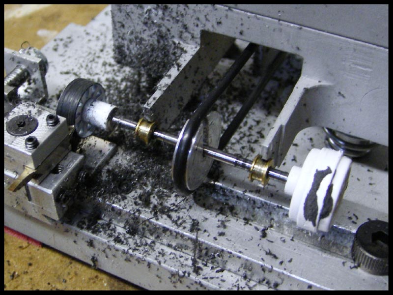
The easiest way to clean off the Tire Razor is to use a can of compressed air to spray off all the debris. If you can spend the money on a can I suggest you do it. The plastic shavings can be a pain to brush or wipe away and you can use the air while the Razor is still under power. This can also be helpful when truing wheels and tires.
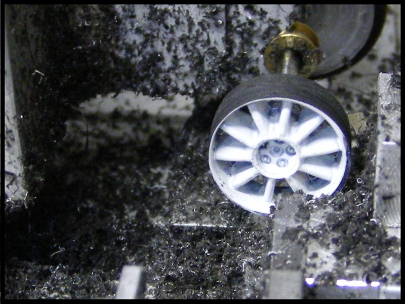
I can tell you one hint that will cut your cutting time and effort by 1/3. Review the picture below.
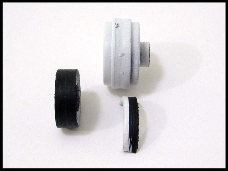
Above you have the complete wheel (top), the almost finished insert after it was cut off (left) and the piece at the bottom is the amount of the wheel cut off on the backside of the wheel. Matt used the utility knife to do this, but as I mentioned before you could use the saw blade included with the lathe to accomplish this task. This is the 1/3 less cutting I was talking about once it’s cut away from the backside of the wheel.
Here is the wheel cut down to the diameter of a SCX Pro Wheel. We actually took it a tad too far and a dab of glue would solve this issue. However, if you have a pair of calipers to gauge where to stop, it would be a great help. If not, then you just have to stop and see if you can slide the wheel over the end of the insert before cutting it off. Check often once you start to get close to the right diameter. If you go too far, there’s no turning back.
Here’s the insert sitting in the SCX wheel. The next steps are sanding and drilling the back of the insert until I reach the desired mounting depth within the wheel. The ending diameter of the insert is pretty close to the inside of the SCX wheel.
Observations
Looking at the lathe I can see that it’s probably a pain in the #@% to build and that it’s made of the same quality materials as the Tire Razor. I found myself thinking, “This is insane and overkill.” The only inserts I’ve ever made where from 1/24 models for a couple of H&R Racing chassis’ I’ve done in the past. I sanded them slowly by hand until they fit just right. A tool like this could have cut a 2 hour ordeal down to 20 minutes. I still don’t know how much I will use it, but I see myself lending it to Matt to use for his new found love of scratch building cars. I’m just not in that frame of mind with the hobby and either is my wallet.
I can use it on stock plastic wheels to true up the sides of that wheel that has extra material and causes the edges of the tire to sit higher than the middle of the tire. Yes, it will work for that use too.
Matt thought it did its job and he recalled sanding down 3 sets of 4 wheels for his 3 SCX Abarths with his Area 3. The hardest part with sanding a plastic wheel down is controlling the heat level of the plastic. You go too fast and hard and the plastic melts. Matt quickly pointed out, “There’s no heat doing it this way.” The 12 wheels took him forever to sand down to size when he replaced the stock wheels with some Ranch Design aftermarket wheels. “It works,” he says at the end of one of the videos.
Here are some callouts Matt and myself discussed and feel deserve to be mentioned about the lathe.
1. It’s handmade and very well, but it’s not going to beat an actual lathe. Keep this in mind.
2. The black control knob is so close to the working parts that it’s awkward to operate with big fingers. Extending the knob further out would be more comfortable to the user.
3. The need for multiple sized Hex Drivers to make all the adjustments to the lathe. If you don’t have them you will have to buy them.
4. You need a Tire Razor to use it. Ambitious folks might be able to adapt the lathe to another brand truer. (shrug)
5. Backlash and play within the cutter base. It affects the cutting of the wheel a bit once you start to apply the pressure of the tip to the wheel.
Will it get worse the more that you use it? I can’t answer that question. The video below shows the movement:
Judgment Day
The Tire Razor lathe attachment is well made for a guy designing and building it in his spare time. There’s no doubt about that fact. I know I don’t have the tools or knowledge to make it. If you already have a Razor and want something to cut wheels down to make custom or more period specific wheels for your slot projects, you’ll likely be satisfied with this lathe. It’s a space saver compared to a full blown lathe purchase, but you’ll be more limited for uses versus the real thing. It beats sanding down plastic wheels with just a tire truer and doesn’t create heat which is plastic’s #1 enemy. The cost of $85 is reasonable for a product such as this attachment. Your prayers may be answered If you’re tired of being limited to existing wheel inserts in the slot car market. If you have that old rare model kit to convert over to a running car and it HAS TO HAVE the original model’s wheel on it to look right…problem solved.
I thank Jon (scrjon) for supplying the Tire Razor Lathe for review and I hope I’ve given a fair and informative review to help you make a decision on purchasing the lathe and/or the Tire Razor with this 2 Part Review. Feel free to contact me with any questions and I will do my best to answer them.
Eric Crooper
AKA Legionofone