
Scalextric Plug-n-Go Digital Chips
Photos & Text Courtesy of Scalextric

The JGTC cars released by Scalextric in May 2006 were developed to include a ‘Plug-n-Go’ digital chip solution for the Japanese market. The cars are available in Japan with and without a chip and sold by Takara. In all other markets, the cars are only available with a ‘blank’ digital module and are sold as standard Scalextric cars. The module is fitted but does not contain a digital chip. A ‘blank’ module can be upgraded to digital by fitting our standard C7006 chip to the existing ‘blank’ digital module.
This is how it is done in a few easy steps. The car body does not need to be removed from the chassis and all the existing internal wiring to the car remains as is. You do not need to separate the car body from the chassis. You will need a small screw driver, wire cutters, file and soldering iron.
|
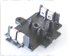
Step 1. Remove digital module.
Remove the dummy module from the base of the car. One screw is all that holds it to the chassis. Remove the screw then gentry prise the module out vertically.
|
|
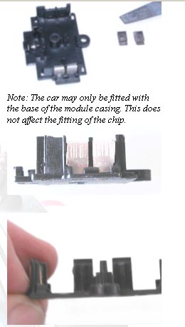
Step 2. Separate the contact clips.
Separate the two halves of the
module and gently remove the two metal clips.
|
|
Step 3. Adjust the sensor boss
height. Reduce the height of the central light sensor boss by about 3mm so that the light sensor pushes through from inside and sits recessed by 2 mm in the mouth of the hole (as viewed from beneath the car). It may also be required to enlarge the hole a little to allow the light sensor to fit all the way in so that the small circuit board holding the sensor rests up against the boss when fitted.
|
|
Offer the sensor and its circuit
board up to the boss to see that fitment is good. Note that the sensor must
not protrude lower than the chassis. The sensor should remain recessed by
about 2mm. |
|
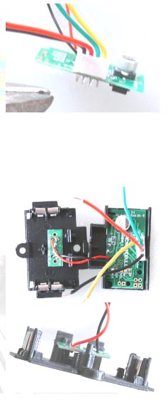
4. Prepare the C7006 Digital Chip assembly.
Remove the excess length of the four soldered pins that form part of the plug/socket that holds the two braid wires and two motor wires. This is necessary to allow the board not to foul the inside of the module casing. After cutting them off, ensure that there is no contact between each of the four pins.
Reduce the length of the four wires
attached to the plug/socket. These wires need to be soldered
to the four metal contact plates, so ensure there
is enough length or wire to enable this to be carried out. |
|
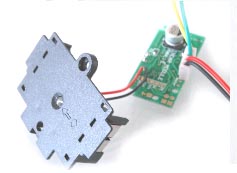
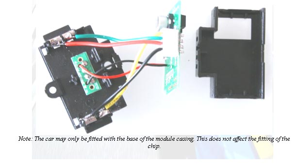
5. Install the digital chip in the module casing.
Fit the light sensor and the main circuit board to the module casing. Refer to the picture for the correct orientation.
Solder the green and red wires from the chip assembly to the metal contacts on the left hand side of the module casing (i.e. the contacts on the left-hand side of the car. See picture of car chassis layout.
Then solder the yellow and black wires to the contact clips on the right hand side of the module casing. |
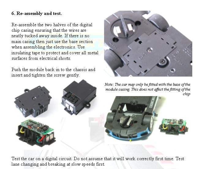
Fault Finding.
Possible error conditions are as follows:
1: Car goes backwards. Action: Reverse the motor wires.
2: Car doesn’t move. Action: Check that the motor wires, metal plates, guide braids, guide blade metal plates are making contact. Also check that the motor works.
3: Lane changing and breaking do not work. Action: Reverse green and yellow wires
For More Information Please Contact Your Local Scalextric Dealer Or Log To The Website Today