08/24/2010
 Step #2 - Adjustable chassis height: The XLOT chassis has independent height adjustments for both the front and the rear of the chassis. 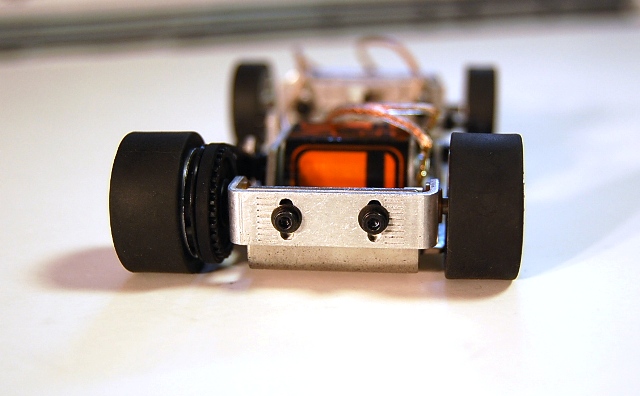 Both front and rear there are two screws that can be loosened with the 1,5mm allen key. Small notches have been stamped in to the chassis to help you adjust both sides evenly when making adjustments. The two rear screws are right on the outside back of the chassis bewteen the rear wheels... 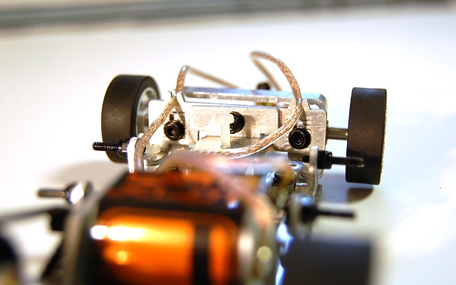 The front two adjustment screws also face the rear of the car, to the inside of both front wheels and close in line to the front axle. Clearly you could leave these as they come from the factory but I did adjust the front axle height on my car to close the gap a little between the top of the front tires and the fenders. 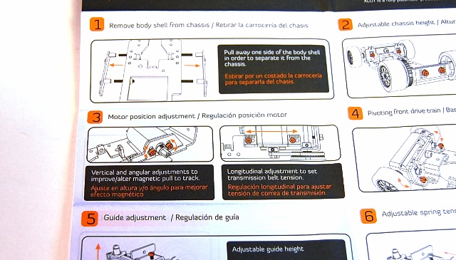 Step #3 shows how to adjust the XLOT's motor position. The two screws on either side of the pinion allow for tilting the motor in its mounting bracket and two screws that secure the motor bracket to the chassis which allows you to move the motor closer to, or away from, the rear axle. Notice on the instructions that 'verticle and angular adjustment' is said to 'improve/alter magnetic pull to the track' but I left the motor flat in the test car. I also didn't alter it's forward position in the chassis for my tests as I wanted to see how it ran straight from the factory. 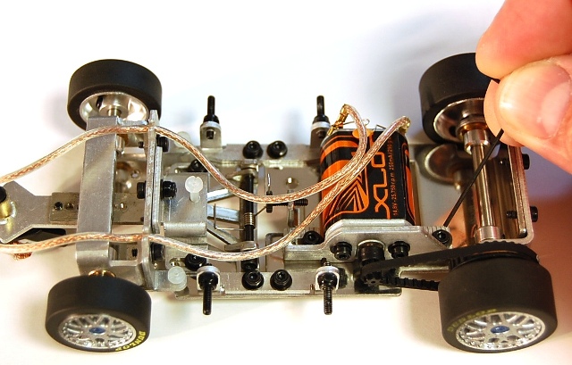 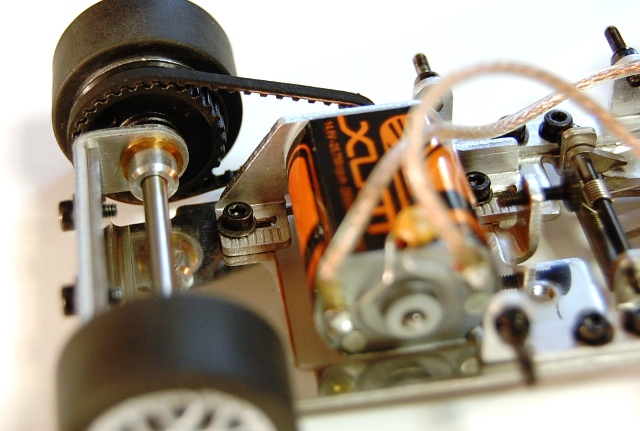 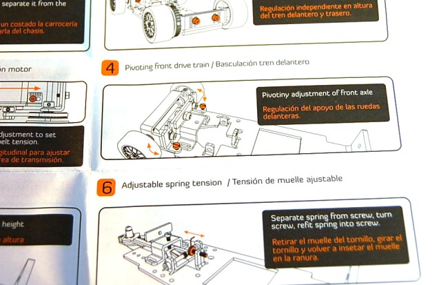 Step #4 above shows the first of the white plastic screws you can turn which for this part limits or allows for pivoting of the front axle bracket. As I mentioned earlier I had slightly raised the front axle in the chassis to close the gap between the tires and the fenders and because of that I turned these white screws down a little so that the pivoting was reduced to make sure the tires didn't contact the fenders. The tapered end of the 'multi-wrench' can be used to make these adjustments but I found for these screws I needed to use the wrench as I couldn't get my fingers in to the tight spaces. 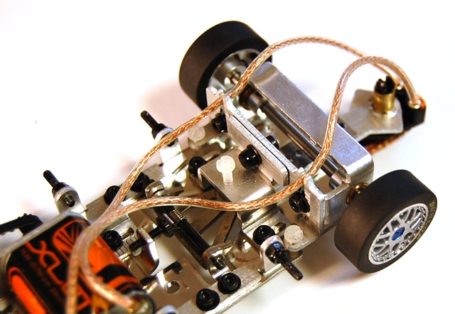 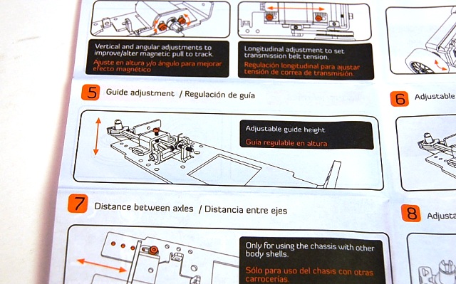 The center white screw I could easily adjust with my fingers as needed. This screw, step #5, is to adjust one aspect of the XLOT guide arm. Screwing this screw down all the way, as you'll see, pushes the guide arm down far enough to give the wheels of the car a good 5/8 inch of lift off of the track surface. 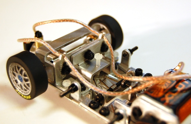 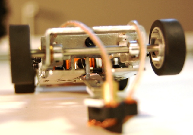 I find this amount of adjustment curious, as I'm not quite certain I see the need for that much lift by the guide, but the ability to adjust the arm is there if you find a practical application for doing so. 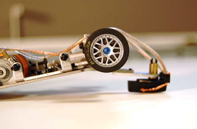 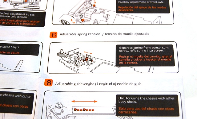 Step #6 also related to the guide although this function adjusts the spring tension on the guide drop down arm. A thin wire spring wraps around a a long screw that acts more or less as the pivot for the guide arm and with one end applying direct pressure to the guide arm the other end rests in a special notched screw that can be adjusted to strengthen or lessen the tension being applied to the guide arm. 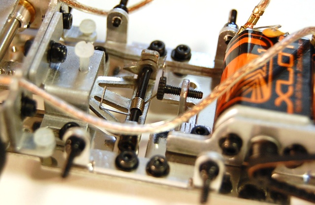 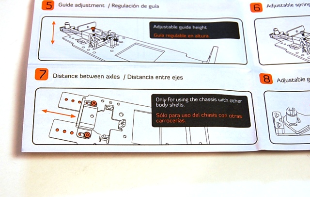 Instruction #7 allows you to lengthen the chassis, or change the distance between axles although the instructions also point out that this is really for using a different body shell that would require a change in the car's wheelbase. 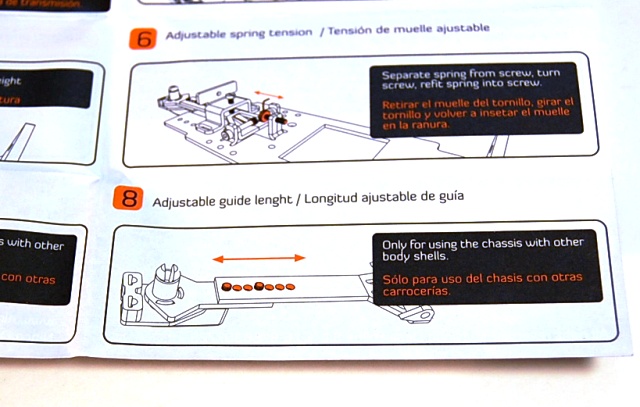 Step #8 brings us back to the guide arm, this time showing how you can change the overall length of the guide lead on the chassis. Out of the box the guide is set just as the drawing shows which it all the way out on the guide arm. You could shorten this but the body shell of the Porsche 997 body provides for ample room for this length of guide lead so whether you decide to change this would be a personal handling preference. 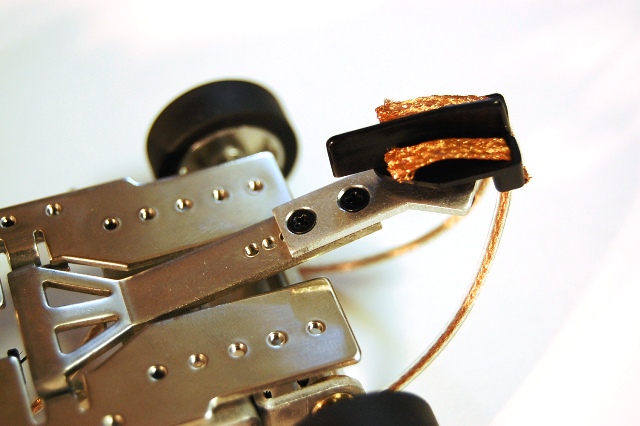 While the instructions don't discuss this the guide post passes, and rotates easily inside of, a piece of brass tubing. Even so there is a small amount of verticle play in the guide post which could be shimmed if you feel the need. 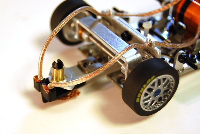 Thanks Go To MRC For Sponsoring This Review!
|